Cisco
PPPoEサーバ/クライアント設定例
構成図
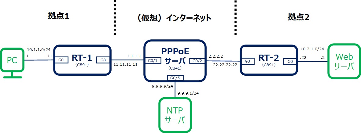
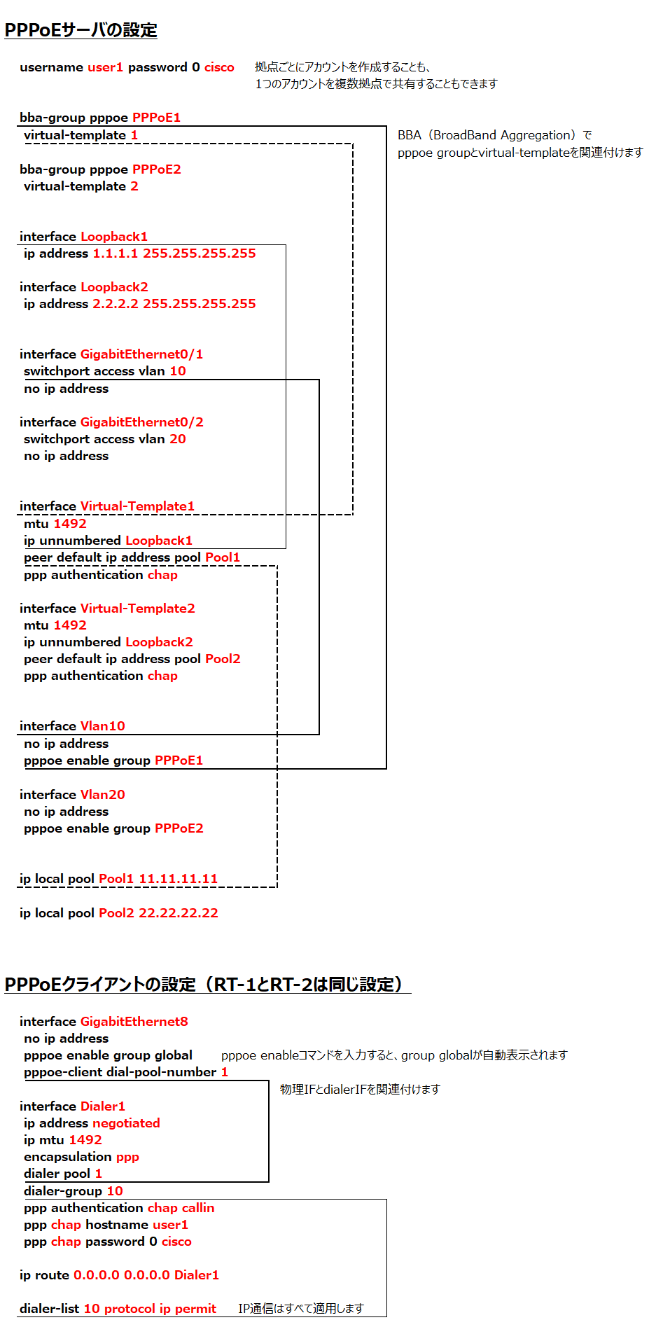
PPPoE+NAT+ACLのコンフィグからPPPoEの設定箇所をピックアップします。
設定の紐づきをアンダーラインで表しています。RT-1のみ。
PPPoEの接続状態確認
PPPoEサーバからIPアドレスが払い出されていることや、ルーティングテーブルで正常に接続できていることを確認できます。
RT-2#show ip interface brief
Interface                  IP-Address      OK? Method Status                Protocol
Async3                     unassigned      YES unset  down                  down
BRI0                       unassigned      YES NVRAM  administratively down down
BRI0:1                     unassigned      YES unset  administratively down down
BRI0:2                     unassigned      YES unset  administratively down down
Dialer1                    22.22.22.22     YES IPCP   up                    up
FastEthernet0              unassigned      YES NVRAM  administratively down down
GigabitEthernet0           unassigned      YES unset  up                    up
GigabitEthernet1           unassigned      YES unset  down                  down
GigabitEthernet2           unassigned      YES unset  down                  down
GigabitEthernet3           unassigned      YES unset  down                  down
GigabitEthernet4           unassigned      YES unset  down                  down
GigabitEthernet5           unassigned      YES unset  down                  down
GigabitEthernet6           unassigned      YES unset  down                  down
GigabitEthernet7           unassigned      YES unset  down                  down
GigabitEthernet8           unassigned      YES NVRAM  up                    up
NVI0                       unassigned      YES unset  administratively down down
Virtual-Access1            unassigned      YES unset  up                    up
Virtual-Access2            unassigned      YES unset  up                    up
Vlan1                      10.2.1.22       YES NVRAM  up                    up
RT-2#
RT-2#
RT-2#show ip route
Codes: L - local, C - connected, S - static, R - RIP, M - mobile, B - BGP
       D - EIGRP, EX - EIGRP external, O - OSPF, IA - OSPF inter area
       N1 - OSPF NSSA external type 1, N2 - OSPF NSSA external type 2
       E1 - OSPF external type 1, E2 - OSPF external type 2
       i - IS-IS, su - IS-IS summary, L1 - IS-IS level-1, L2 - IS-IS level-2
       ia - IS-IS inter area, * - candidate default, U - per-user static route
       o - ODR, P - periodic downloaded static route, H - NHRP, l - LISP
       a - application route
       + - replicated route, % - next hop override

Gateway of last resort is 0.0.0.0 to network 0.0.0.0

S*    0.0.0.0/0 is directly connected, Dialer1
      2.0.0.0/32 is subnetted, 1 subnets
C        2.2.2.2 is directly connected, Dialer1
      10.0.0.0/8 is variably subnetted, 2 subnets, 2 masks
C        10.2.1.0/24 is directly connected, Vlan1
L        10.2.1.22/32 is directly connected, Vlan1
      22.0.0.0/32 is subnetted, 1 subnets
C        22.22.22.22 is directly connected, Dialer1
RT-2#